GUI walkthrough
This page provides a complete, field-by-field walkthrough of the WAH-i (Graphical User Interface) for microphone-array design and optimisation. All panels and controls correspond to the numbered regions shown in the GUI.
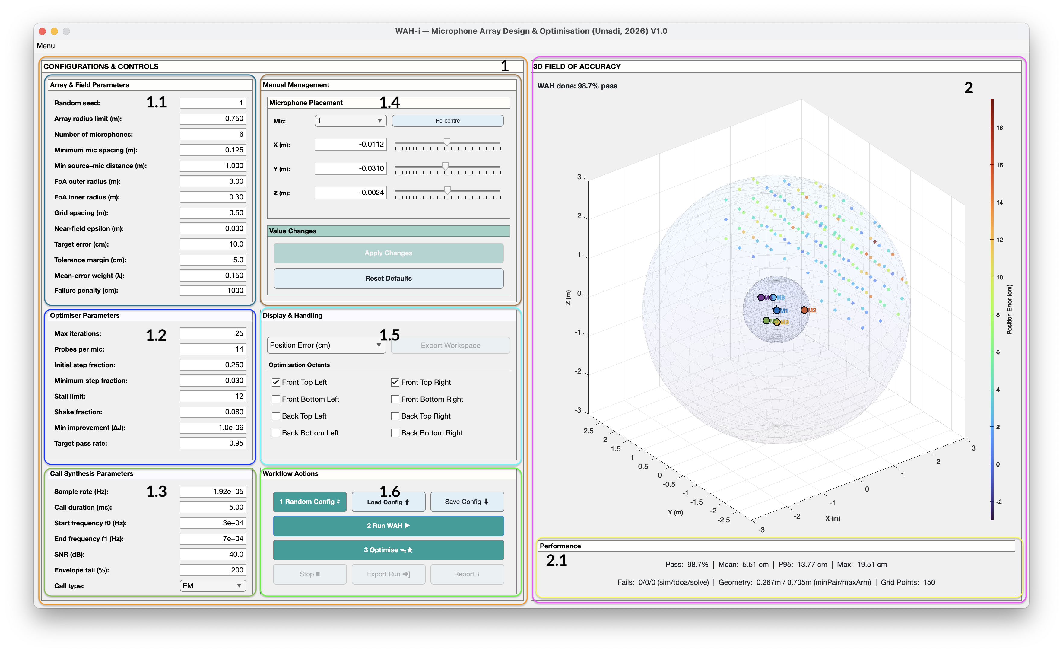
1) Configurations & Controls (left panel)
This panel defines the geometry, evaluation field, optimisation behaviour, and signal model. Changes in this panel are not applied until explicitly committed.
⚠️ Important: Any change in this section must be committed using Apply Changes before evaluation or optimisation.
1.1 Array & Field Parameters
These parameters define physical constraints and the Field of Accuracy (FoA) over which localisation performance is evaluated.
-
Random seed Sets the random number generator seed used when creating random geometries.
Using a fixed seed ensures full reproducibility across runs. -
Array radius limit (m) Maximum allowed distance of any microphone from the array centre. This represents a physical arm-length or mounting constraint.
-
Number of microphones Total microphone count used in the array.
-
Minimum mic spacing (m) Enforces a minimum inter-microphone distance to prevent clustering and numerically unstable geometries.
-
Minimum source–mic distance (m) Excludes source positions that are too close to microphones, avoiding near-field degeneracies and unrealistically large TDOA gradients.
-
FoA outer radius (m) Outer boundary of the evaluation volume.
-
FoA inner radius (m) Inner exclusion radius around the array centre.
-
Grid spacing (m) Spatial resolution of the evaluation grid.
Use coarse spacing for exploration, finer spacing for refinement. -
Near-field epsilon (m) Numerical buffer applied to source–mic distance calculations.
-
Target error (cm) Defines the localisation error threshold considered a pass.
-
Tolerance margin (cm) Soft margin applied around the target error.
-
Mean-error weight (λ) Weighting factor applied to mean error in the optimisation objective.
-
Failure penalty (cm) Penalty assigned to failed localisation points.
1.2 Optimiser Parameters
Controls how WAH-i explores geometry space during optimisation.
-
Max iterations Maximum number of optimisation steps.
-
Probes per mic Number of trial perturbations evaluated per microphone per iteration.
-
Initial step fraction Starting fraction of the maximum allowable displacement.
-
Minimum step fraction Lower bound on step size during refinement.
-
Stall limit Number of iterations with no improvement before triggering a shake.
-
Shake fraction Magnitude of random perturbation applied to escape local minima.
-
Minimum improvement (ΔJ) Smallest objective improvement considered meaningful.
-
Target pass rate Desired fraction of FoA points that must meet the target error.
These parameters enable staged optimisation, from coarse exploration to fine refinement.
1.3 Call Synthesis Parameters
Defines the synthetic acoustic signal used for TDOA estimation.
-
Sample rate (Hz) Sampling frequency of the synthetic signal.
-
Call duration (ms) Length of the emitted signal.
-
Start frequency f0 (Hz) Upper bound of the sweep. Also used as the freq for CF cal type.
-
End frequency f1 (Hz) Lower bound of the sweep. Ignored for CF call type.
-
SNR (dB) Signal-to-noise ratio applied to the simulated recordings.
-
Envelope tail (%) Padding applied to the signal envelope.
-
Call type FM (frequency-modulated) or CF (constant-frequency).
1.4 Manual Management — Microphone Placement
Allows direct manipulation of individual microphone positions.
-
Mic selector Choose which microphone to edit.
-
X, Y, Z (m) Cartesian coordinates of the selected microphone.
-
Sliders / edit boxes Adjust positions interactively or numerically.
-
Re-centre Recentres the array about the origin.
Changes here must be committed using Apply Changes.
You can Restore Defaults to start over from the top.
1.5 Display & Handling
Controls what metric is visualised and which regions are optimised.
-
Metric selection Choose between Position Error or Angular Error. Only positional threshold is used in the accuracy estimation. Angular option is for post-hoc check only.
-
Optimisation octants Select which spatial octants of the FoA are included in optimisation. This enables task-specific spatial targeting, e.g. forward-only regions.
1.6 Workflow Actions
Primary workflow controls:
-
1 Random Config ♯ Generates a random geometry consistent with current constraints.
-
Load Config ↑ Loads a previously saved CSV geometry.
-
Save Config ↓ Saves the current microphone geometry to CSV.
-
2 Run WAH ▶︎ Evaluates the current geometry over the FoA.
-
3 Optimise ᯓ★ Starts the optimisation procedure.
-
Export Run → Exports the full run state as a
.matfile. -
Report Generates a summary report of performance and convergence.
2) 3D Field of Accuracy (right panel)
Displays the evaluated spatial field:
- Coloured points represent localisation error magnitude.
- The inner and outer FoA boundaries are visualised as shells.
- Microphone positions are shown at the centre.
- Colour bar indicates error in centimetres.
This view updates after each evaluation or optimisation step.
2.1 Performance Summary
Numerical performance metrics:
- Pass rate (%)
- Mean error (cm)
- 95th percentile (P95) error
- Maximum error
- Failure counts
- Geometry span
- Grid point count
These metrics define the optimisation objective and stopping criteria.
Suggested workflow
- Generate a random configuration or load a known geometry
- Define a coarse FoA and grid spacing
- Run WAH to evaluate baseline performance
- Perform coarse optimisation
- Tighten grid spacing and thresholds
- Re-optimise with smaller step sizes
- Save configuration and export results
This workflow supports rapid iteration while maintaining full reproducibility.